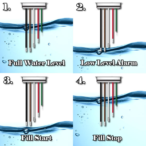
If you are searching for “float switch working principle” or “how does a float switch work” this post should help.
- Old Float Switch Working Principle
- New Float Switch Working Principle
- Single Point Float Switch Working Principle
- Multi-point Float Switch Working Principle
How Old Float Switches Work
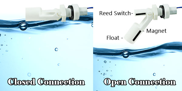
Older Float Switches work by opening and closing circuits (dry contacts) as water levels rise and fall. Typical float switches are normally resting in the closed position, meaning the circuit is incomplete and no electricity is passing through the wires yet.
Old Float Switch Working Principle
Once the water level drops below a predetermined point, the circuit completes itself and sends electricity through the completed circuit to trigger an alarm.
How does the electricity pass through the circuit? The electricity passes through, what are called, magnetic reed switches. Once the water does drop low enough, the reed switches come in contact with each other and complete the circuit, allowing electricity to be passed through them and turn on the alarm. Once the water gets high enough again, the switches break apart and disconnect the circuit.
The Magnetic Reeds Open & Close To Control Water Levels
The magnetic reeds are sealed in a stainless steel or plastic stem. The magnetized reed switches move and down as the water level increases and decreases and are set to come together and break apart at different heights that you specify during installation.
The problem with the way these old float switches work is that they can deteriorate due to poor water quality and electricity passing through them. That’s why Water Level Controls created their own float switch replacement that uses sensing probes to gauge water levels instead of floats.
Float Valves
Other cooling tower operators typically used float valves instead of sensor rods for automatic control of water levels. Float valves use a floating mechanism and arm to gauge water levels and turn on and off pumps. These types of float switches could only do 1 or 2 operations unlike new float switches that can be programmed to handle many automatic operations.
How New Float Switches Work
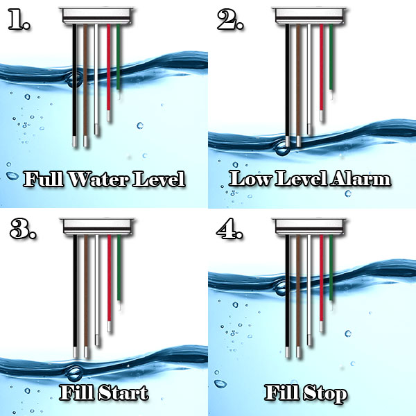
Water Level Control’s float switches work by using probes instead of float switches.
“The sensor probes actually act as their own sensors and do not pass electricity through the probes which keeps them from fouling, degrading and deteriorating. Also, all of the electronics are built into the head so you can connect directly to your control panel. Once the water level is detected by one of the sensors, this causes one of six alarms to be triggered (High Alarm, Low Alarm, Fill Start, Fill Stop, etc). Depending on the type of float switch you have, there can be single point alarm or a multi point alarm that is triggered.” How Do Float Switches Work
Single Point & Multi Point Float Switches
Single point and multipoint float switches allow you more control of your storage tank filling mechanisms and will last 5 times longer than traditional float switches.
How Single Point Float Switches Work
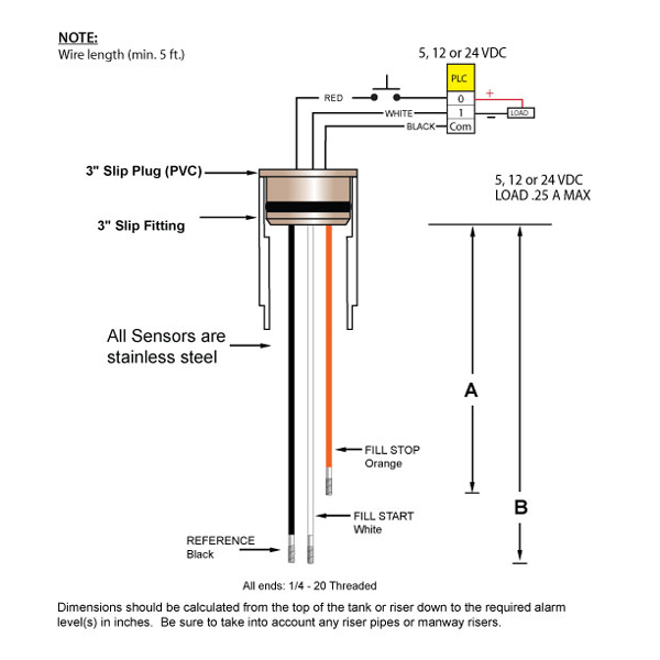
Single point float switches work with 3 sensor rods (Reference, Start & Stop) that work in conjunction to turn on and off your water pump automatically. This helps keep water levels at a consistent level.
How Multi Point Float Switches Work
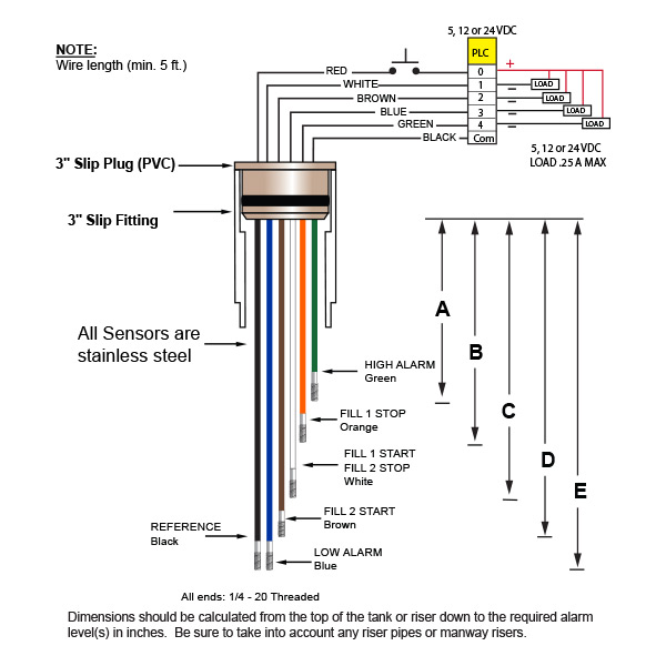
In Multi-point float switches, there are 4-6 sensor rods (High alarm, fill 1 stop, fill 1 start, fill 1/fill 2 stop, fill 2 start, low alarm, reference). These rods can programmed to do multiple tasks such as stop water levels once they reach a predetermined point and start filling water once its drops below a certain level.
The most basic way to explain this is; the sensor probes stick down in the water to detect water levels at different heights, depending on the height of the water, the probes all have different tasks they perform. If the water level is too low, it sets off the low water alarm, if the water is too high, it sets off the high level alarm etc.
Buy Cooling Tower Float Valves
Shop for Cooling Tower Float Valves at Cooling Tower Products.

